The dude
TRX Junkie
I'm saving one of mine to activate the GAU-30mm I hope to mount.
Going to need some serious payload upgrades for that. Like a single cab 3500 upgrade.
I'm saving one of mine to activate the GAU-30mm I hope to mount.
Well, the gun itself only weighs around 600lbs. Figure a couple of hundred pounds more for a decent mount for it. We'll go titanium, just because... and, it looks cool.Going to need some serious payload upgrades for that. Like a single cab 3500 upgrade.
")
I paid for that option to fill the hole in the dash that would otherwise be there if the option was not selected.What else are you guys using them for?
I had that in my Raptor. It was a one-time use button.AUX 1 is the "Wife Ejection Button".........Pano opens, triple airbags mounted in the passenger seat ignite and then......silence....ahhhhhhhh!
No need for me to explain why I have that button!
Super clever the way you wired up the relay. Can you explain the wiring and parts required?I have one aux switch that controls my QTP exhaust cutouts. Another arms the Oracle lightbar ("arm" meaning supplies power to a relay that is triggered by the high beams), so that with the aux switch activated, the light bar is operated by the high beam circuit, meaning the automatic high beams also control the light bar.
See post #15 in this thread, which then points to a post I made in another thread that details how to wire this up.Super clever the way you wired up the relay. Can you explain the wiring and parts required?
Thanks
Haha, yes. I got mine from @BrawlerFab. . .I plan on using one as the power switch to my Nitrous system and another for a Rigid Spectre spot facing backwards for the ass-wipes behind me driving with their high-beams on.
. . .niceHaha, yes. I got mine from @BrawlerFab View attachment 42308
Thanks. They work both ways, in reverse and also stand alone. For the ever so happy individual, who chooses to high beam me.. . .nice
Thanks, they're super bright and @BrawlerFab is an awesome company.. . .nice
You’re a real spy hunter.Rocket launcher.
Machine guns.
Oil slick.
Smoke screen.
Damn trailer control took up my other two.
I wish I was! I don't even have a personal truck anymore because I sold my 19 Laramie. My oil slick now is leaking oil cooler lines on my 06 manual trans dually!You’re a real spy hunter.
Can you provide pics of the wiring to the controller? I'm sorry I'm the worst with wiring and need visualsBy using this exhaust cutout controller:
Universal Exhaust Cut Outs One Touch Controller| Timers.shop
adds several features to give the user the convenience and the full control of the cut-out flap operation.timers.shop
7 wires total are needed to the controller:
- The four wires (+ and -) from each of the two cutout motors
- An ignition-switched power source
- A ground
- An aux switch output
The control module is configurable/programmable from your phone via its own WiFi... you put the module into programming mode by pulsing the switch input 5 times (just push the Aux on and off quickly, and the SSID will show up on your available networks list on your phone). Once you connect to the SSID, just launch a browser, and configure the controller.
You set it up the controller for a single latching switch, meaning when the switch input receives power from the Aux, it runs the motors in the open direction for a set number of seconds. When power on the switch input goes away, the controller runs the motors in reverse for a set number of seconds.
I settled on, I think, 4 seconds each. That seemed to get the valves all the way open, without pinning the motors against the stops.
The end result is a seamless operation - turn the Aux switch on, the cutouts open. Turn the aux switch off, the cutouts close.

It's all hidden away in the box that houses the controller, all wiring is covered in wire loom, and zip-tied out of the way - I'd have to rip everything apart to get any meaningful pictures. Not going through all that...Can you provide pics of the wiring to the controller? I'm sorry I'm the worst with wiring and need visuals
You are the man! Thank you sir for the dummy version!!It's all hidden away in the box that houses the controller, all wiring is covered in wire loom, and zip-tied out of the way - I'd have to rip everything apart to get any meaningful pictures. Not going through all that...
But, the timers.shop provides this image of the controller board:
View attachment 42813
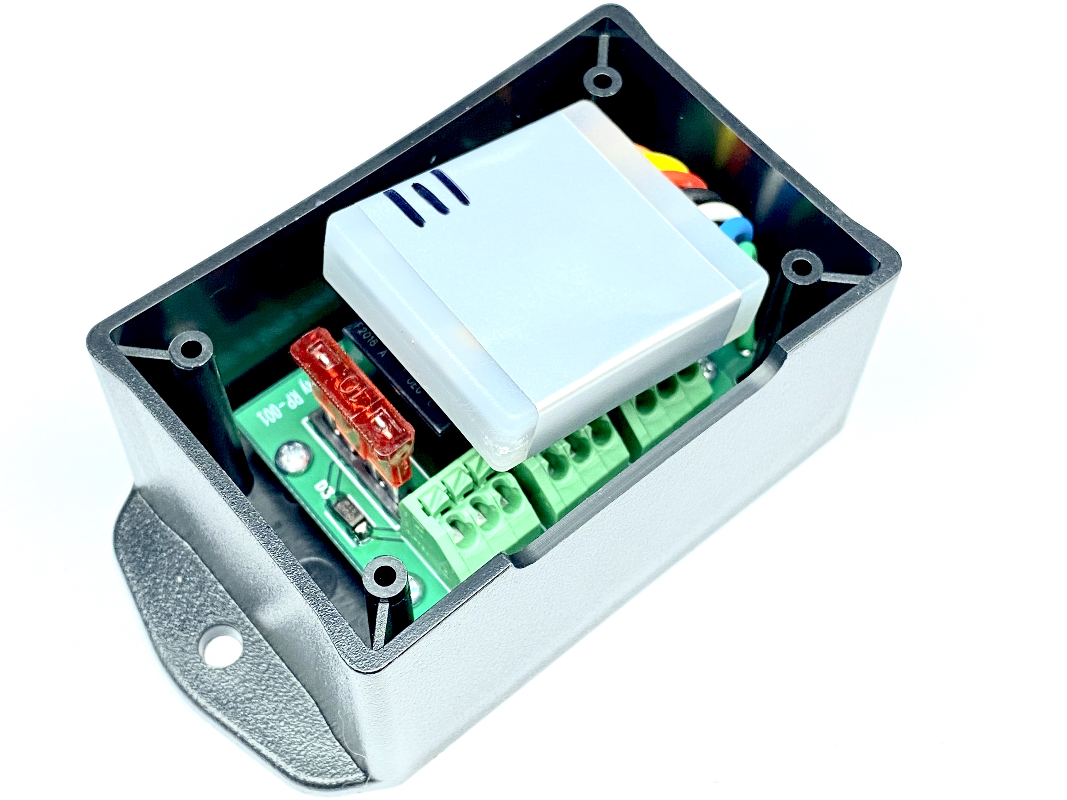
I mounted the controller box on the passenger-side of the engine compartment, mainly because the wires from the cutout motors weren't long enough to make it up the passenger frame rail, then across the front of the engine bay over to the driver's side. There's plenty of room on the pass. side, and I just screwed the mounting flange of the housing to the factory black plastic "shelf" that's there. This is the box that houses the controller above:
View attachment 42818
At any rate, take the four wires from the cutout motors (two red, two black), strip off about 1/4" of insulation, and put them into the four terminals labeled M1+, M1-, M2+, and M2-. Red to +, black to -. It doesn't really matter if you mix them up - just as long as reds go to +, and blacks go to -.
Then run three more wires (you supply these wires - I suggest red, black, and blue). Black goes into the GND terminal, red into the 12V terminal, and blue into the TR1 terminal. For all of these terminals, you strip back about 1/4"-3/8" of wire, push down the little tab with the diagonal slot in it (use a small flat screwdriver), insert the wire, then release the tab. It's a spring-loaded jaw that grabs the wire - a gentle tug on the wire will confirm that it's got ahold of it. If the wire pulls right out, you missed.
I ran these three wires across the front of the engine bay, over to the PDC (fuse box). The black wire goes to one of the ground terminal studs on the driver's inner fender. The red wire goes to an ignition-switched +12V source (I used a fuse tap inside the PDC to tap fuse #60). The blue wire connects to your AUX switch output.
Here's a picture of the fuse tap:View attachment 42825
The original 20A fuse (yellow) is on the bottom of the fuse tap, while a 10A fuse (red) provides protection to the tapped wire that feeds the cutout controller. I notched the PDC cover to accommodate the wire.
Here's a shot of the wiring coming across from the controller:
View attachment 42826
Here you see the red wire coming out of the PDC, and it goes into the wire loom. You can also see the black wire coming out of the wire loom, connecting to one of the vehicle grounding studs (the red stud w/ the red nut). Also going into that wire loom is one of the Aux switch wires (the pink w/ blue stripe) - that connects to the blue wire.
All three of those wires (red, black, blue) are inside that wire loom that runs up, then across the top and over to the right... that's leading back to the exhaust controller on the pass. side.
That's really all there is to it. On a wiring difficulty scale of 1-10, I'd give this one about a 0.7